HMIx practical guides
Build a horizontal tank with dynamic SVG in WinCC Unified
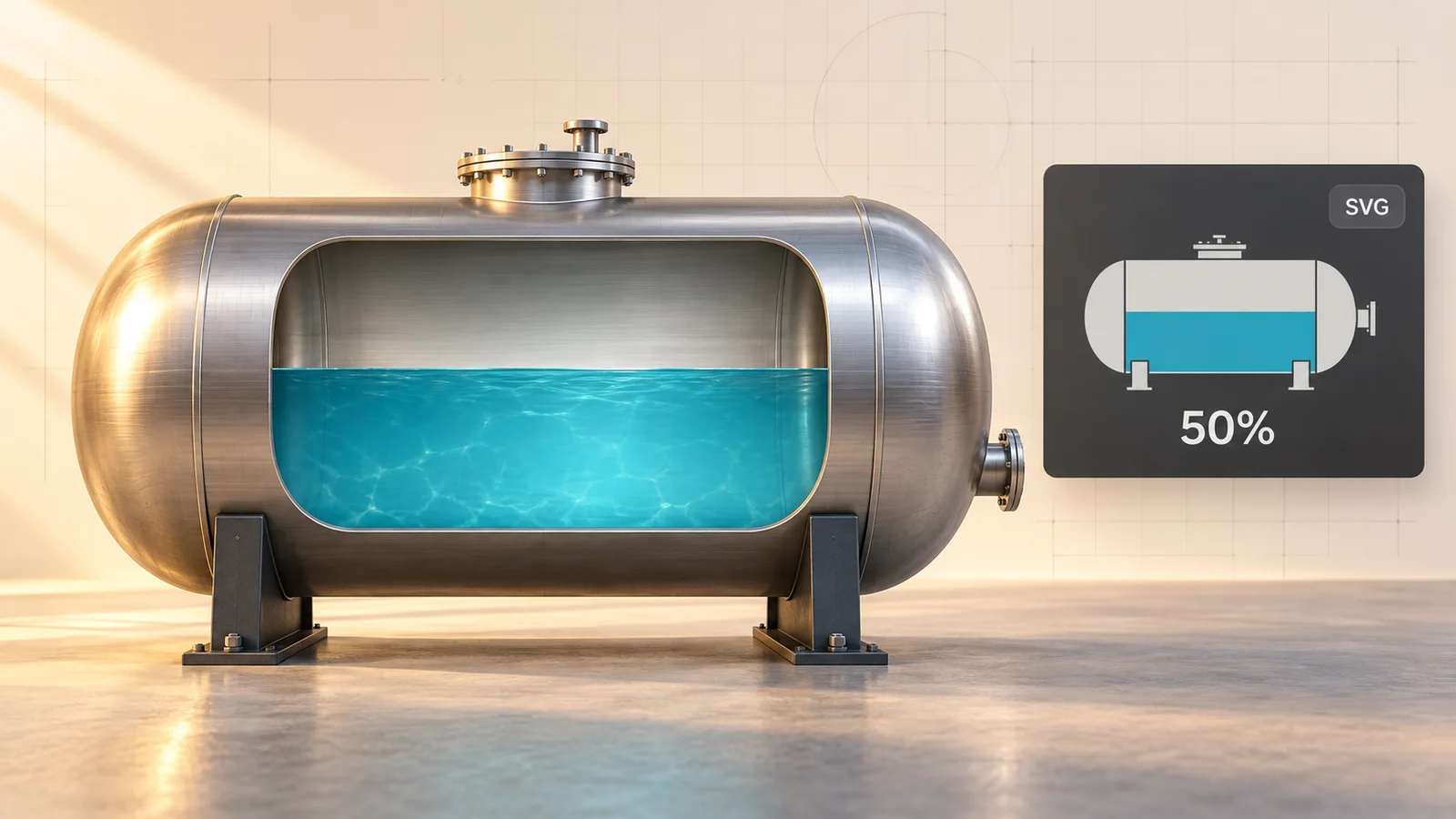
A horizontal tank, a metallic finish and a level driven by one tag. Learn to build this dynamic SVG and test it in TIA Portal, without JavaScript or separate images for each state.
Guide environment: TIA Portal / WinCC Unified V21.1. Check the example’s import and operation on your target device.
What is a dynamic SVG?
SVG describes a picture with shapes and lines instead of a fixed grid of pixels. That makes it useful for symbols that must stay sharp at different screen sizes: tanks, valves, motors and indicators.
For a parameterised WinCC Unified widget, the file uses the .svghmi format. It adds an interface to the drawing, with parameters such as FillLevel or a colour. TIA Portal exposes those parameters so you can connect them to HMI tags. A value changes the drawing; you do not need 101 separate images for a 0–100 percent tank.
A normal .svg can be used as a graphic, but simply renaming it to .svghmi does not add a dynamic interface.
- Use a dynamic SVG for fill levels, equipment states, changing colours or simple motion driven by values.
- Choose a CWC when you need a richer web interface, a custom table or several interactions.
- Keep the first graphic small and simple so you can see exactly what each parameter does.
HMIx offers hundreds of free HMI resources to download. Start with a control from the catalogue, or describe your idea to the HMIx AI generator and create a resource you can adapt to your project.
Siemens · Managing dynamic SVG graphicsSiemens · Supported SVG format and restrictions
What you need for the first test
Use a test project with a Unified device and an empty screen, plus compatible WinCC Unified Runtime or simulation components. This guide follows V21.1; other WinCC editions and older versions can differ.
- For manual drawing, use a vector editor such as Inkscape and a text editor to add the HMI interface.
- For an immediate test, download our small .svghmi example below. A PLC is not needed.
- Use shapes and effects supported by WinCC Unified. A good-looking SVG in a browser does not prove that every element will work on the HMI device.
Draw a horizontal tank with one parameter
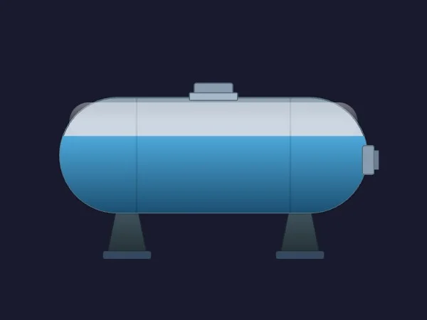
The tank combines a rounded outline, two supports and gradients for a metallic finish. The liquid is a separate rectangle clipped inside the tank. Only one parameter changes: FillLevel, from 0 to 100.
Draw the static parts
Draw the horizontal body, supports and top hatch. Define a 400 × 250 viewBox. Put the tank outline inside a clipPath to keep the liquid within the rounded ends.
Add the HMI interface
In a text editor, add the Siemens HMI namespaces and an hmi:self section. Define FillLevel with hmi:paramDef, type number and default 50. Our complete file already supplies this structure.
Bind the liquid shape
Link hmi-bind:height and hmi-bind:y to ParamProps.FillLevel. As the rectangle gets taller, its upper edge rises while the bottom stays fixed. The clipPath contains the liquid and Converter.Bounds limits the display to 0–100.
Save as .svghmi
Save the XML as UTF-8 with the exact extension .svghmi, not .svghmi.txt. Keep an editable backup. After adding HMI bindings, avoid resaving through a generic vector editor that may strip the Siemens attributes.
Here, FillLevel means percentage of liquid height. In a horizontal tank this generally differs from percentage of volume. Litres or volume require a conversion based on the tank’s geometry.
Complete .svghmi file with FillLevel (0–100). XML structure and expressions checked; validate importing it in WinCC Unified V21.1.
View the example code
Optional: the download contains the complete example. You do not need to type this code to follow the test.
HmixHorizontalTank.svghmi
<?xml version="1.0" encoding="UTF-8"?>
<!DOCTYPE svg PUBLIC "-//SIEMENS//DTD SVG 1.0 TIA-HMI//EN" "http://svg.siemens.com/hmi/svg10-hmi.dtd">
<svg xmlns="http://www.w3.org/2000/svg"
     xmlns:xlink="http://www.w3.org/1999/xlink"
     xmlns:hmi-bind--xlink="http://svg.siemens.com/hmi/bind/xlink/"
     xmlns:hmi="http://svg.siemens.com/hmi/"
     xmlns:hmi-bind="http://svg.siemens.com/hmi/bind/"
     xmlns:hmi-element="http://svg.siemens.com/hmi/element/"
     xmlns:hmi-feature="http://svg.siemens.com/hmi/feature/"
     xmlns:hmi-event="http://svg.siemens.com/hmi/event/"
     width="400" height="250" viewBox="0 0 400 250" preserveAspectRatio="xMidYMid meet">
  <hmi:self type="widget" displayName="HMIx Horizontal Tank"
            name="extended.HmixHorizontalTank" version="1.0.0">
    <hmi:paramDef name="FillLevel" type="number" default="50" />
  </hmi:self>
  <defs>
    <hmi:localDef name="SafeLevel" type="number"
      hmi-bind:value="{{ Converter.Bounds(ParamProps.FillLevel, 0, 100) }}" />
    <linearGradient id="steel" x1="0" y1="0" x2="0" y2="1">
      <stop offset="0" stop-color="#7f949f" />
      <stop offset="0.28" stop-color="#edf3f5" />
      <stop offset="0.52" stop-color="#bdcbd1" />
      <stop offset="1" stop-color="#667d88" />
    </linearGradient>
    <linearGradient id="water" x1="0" y1="0" x2="0" y2="1">
      <stop offset="0" stop-color="#4cc4df" />
      <stop offset="1" stop-color="#176184" />
    </linearGradient>
    <clipPath id="inside"><rect x="40" y="60" width="320" height="120" rx="60" /></clipPath>
  </defs>
  <!-- One parameter changes liquid height, not volume percentage. -->
  <path d="M100 170L90 220H130L120 170M280 170L270 220H310L300 170" fill="#405866" stroke="#273d49" stroke-width="2" />
  <path d="M86 224H134M266 224H314" stroke="#607987" stroke-width="8" />
  <rect x="180" y="43" width="40" height="17" rx="3" fill="url(#steel)" stroke="#546e7a" />
  <rect x="175" y="54" width="50" height="8" rx="2" fill="#adbec7" stroke="#546e7a" />
  <rect x="40" y="60" width="320" height="120" rx="60" fill="url(#steel)" />
  <g clip-path="url(#inside)">
    <rect id="liquid" x="40" y="120" width="320" height="60" fill="url(#water)"
      hmi-bind:height="{{ LocalProps.SafeLevel * 1.2 }}"
      hmi-bind:y="{{ 180 - LocalProps.SafeLevel * 1.2 }}" />
    <path d="M120 60V180M280 60V180" stroke="#254b60" stroke-opacity="0.22" stroke-width="2" />
    <path d="M55 78H345" stroke="#ffffff" stroke-opacity="0.28" stroke-width="8" />
  </g>
  <rect x="40" y="60" width="320" height="120" rx="60" fill="none" stroke="#546e7a" stroke-width="2" />
  <rect x="354" y="109" width="14" height="28" rx="2" fill="url(#steel)" stroke="#546e7a" />
  <path d="M369 115V131" stroke="#8ea5b1" stroke-width="6" />
</svg>
Load it as a dynamic widget in TIA Portal
Put the file in the project
Open the project folder and create UserFiles\SVGControls if needed. Copy HmixHorizontalTank.svghmi there. For this workflow, the actual .svghmi file belongs here, not a ZIP.
Open Dynamic widgets
Open the Unified screen and go to Tools → Dynamic widgets. Refresh the palette after adding or changing the file; if a newly added file is not listed, reopen the project.
Place and inspect it
Drag HMIx Horizontal Tank onto the screen. In its properties, locate the user-defined FillLevel parameter and set a static value of 50. Check that the drawing is visible before linking a tag.
Use Dynamic widgets for this file. Importing an ordinary SVG into the graphics collection is a different workflow and does not create these parameters.
Siemens · Managing dynamic SVG graphicsSiemens · Updating dynamic SVG graphics
Make the level change in Runtime
Create an internal value
Add an internal HMI tag named TankLevel of a numeric type such as Real, with no PLC connection. This is the value you will change by hand.
Connect the parameter
Select the tank and set the FillLevel parameter's dynamization to Tag, then select TankLevel. The parameter name belongs to the SVG; the tag name belongs to your HMI project.
Add a numeric I/O field
Place it beside the graphic, select input/output mode and link its process value to the same TankLevel. Set input limits to 0 and 100 where available.
Compile and try three values
Make this the start screen, compile the HMI and start its supported simulation or your Unified PC test Runtime. Open the Runtime client, sign in if required, and enter 0, 50 and 100 in the I/O field. Confirm each entry and watch the liquid move.
Check resizing and reopening
Reopen the screen to verify the current value. Also test a second instance at another size: the outline should stay clear and the fill must remain inside it.
The slider below illustrates the expected result. It is separate from TIA Portal and does not communicate with your project.
First, see what should happen
Move the slider: liquid rises within the tank outline. FillLevel represents height, not volume.
Your test is successful when…
At 0 the tank is empty, at 50 the liquid reaches half its height, and at 100 it reaches the top. The liquid stays inside the outline and agrees with the I/O field after reopening the screen.
Common problems, simple checks
- It is not in Dynamic widgets: check UserFiles\SVGControls, the real file extension, valid XML and the HMI interface, then refresh the palette.
- The tank appears but does not fill: check that the file contains HMI bindings and that FillLevel is bound to the same tag as the I/O field.
- The level fills downward: the liquid's top position must change along with its height. Our example keeps the bottom fixed.
- It looks different from the vector editor: simplify unsupported effects, CSS and font dependencies. Check the actual target rather than relying only on a browser preview.
- An update loses a binding: renaming or removing parameters, or changing their types, can break existing instances. Preserve the interface or reconfigure affected instances.
Once the direct-screen example works, you can explore dynamic SVG library types for reuse in screens and faceplates. That is a useful next step, not a requirement for this first test.
Siemens · Updating dynamic SVG graphicsSiemens · Dynamic SVG graphics as library types
Frequently asked questions
Is an SVG automatically dynamic in Unified?
No. A static SVG contains a drawing. A parameterised .svghmi also needs the Siemens interface and bindings. Changing the extension alone is insufficient.
Do I need JavaScript for this tank?
No. The fill uses expressions inside the SVGHMI and a tag binding in TIA Portal. More elaborate interactions may be easier with a CWC.
Can I use the same file in every WinCC edition?
Do not assume that. Select the correct target in HMIx and check the resource's compatibility. This walkthrough is for WinCC Unified; versions and other WinCC editions have their own limits.